- Atwood Hydro Flame Furnace Manual
- Atwood Hydro Flame Furnace Operation
- Atwood Hydro Flame Furnace Thermostat Manual
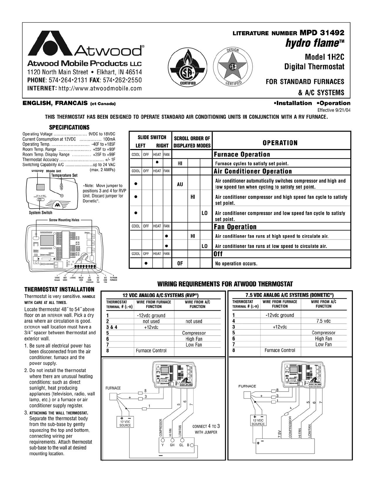
- Atwood Hydro Flame Thermostat Manual Diagram
View and Download Atwood HYDRO FLAME 1H2C user manual online. Atwood Mobile Products Thermostat User Manual. HYDRO FLAME 1H2C thermostat pdf manual download. The Hydro Flame RV Furnace is one of the first units you'll encounter in your search. This is a lightweight, compact model, weighing in at just 23 pounds with dimensions of 11-3/8″ high, 8-3/8″ wide, and 20-1/2″ deep.
LITERATURE NUMBER MPD 31493 | |
hydro flameTM | |
Model 2H2C | |
Two Stage Furnace | |
9 | Digital Thermostat |
FOR TWO STAGE FURNACE | |
ENGLISH, FRANCAIS (et Canada) | •Installation •Operation |
Effective 1/08 |
THIS INSTRUCTION MANUAL IS FOR USE BY AN AUTHORIZED SERVICE TECHNICIAN TO INSTALL AN ATWOOD - hydro flame TM FURNACE. INSTALLER: LEAVE THIS MANUAL WITH APPLIANCE. CONSUMER: RETAIN THIS MANUAL FOR FURTHER REF-ERENCE. This furnace design has been certified for installation in recreation vehicles as a MSP Category III furnace. Atwood / Hydro Flame EXPLODED PARTS VIEWS. Item#15 Thermostat, White, 38453. Not Shown Mud Dauber Screen for Atwood 8500 Series Furnace JCJ M-500.
THIS THERMOSTAT HAS BEEN DESIGNED TO OPERATE STANDARD AIR CONDITIONING UNITS IN CONJUNCTION WITH AN EXCALIBUR 2-STAGE FURNACE.
Atwood Hydro Flame Furnace Manual
Screw Mounting Holes | ||
Mode | Temperature | |
Display Set | Set | |
(OFF) OFF | HEAT (CHAUFFAGE) | M |
(CLIM) COOL | FAN (VENTIL.) | |
System Switch | ||
*Note: Move jumper to |

1
2
3
4
5
6
7
8
positions 3 and 4 for RVP
12VDC
NOT
+12VDC
RELAY
A/C
A/C
A/C
TH FROM
Unit. Discard jumper for
Ground
USED
COM
COM-
HI
LOW
FURNACE
Dometic®.
*
PRESSOR
FAN
FAN
THERMOSTAT INSTALLATION
Thermostat is very sensitive. HANDLE WITH CARE AT ALL TIMES.


Locate thermostat 48˝ to 54˝ above floor on an INTERIOR wall. Pick a dry area where air circulation is good. EXTERIOR wall location must have a 3/4˝ spacer between thermostat and exterior wall.
1.Be sure all electrical power has been disconnected from the air conditioner, furnace and the power supply.
2.Do not install the thermostat where there are unusual heating conditions: such as direct sunlight, heat producing appliances (television, radio, wall lamp, etc.)
or a furnace or air conditioner supply register.
Atwood Hydro Flame Furnace Operation
3.ATTACHING THE WALL THERMOSTAT. Separate the thermostat body from the sub-base by gently squeezing the top and bottom. Pull wires through access hole in base plate. Attach thermostat sub-base to the wall at the desired mounting location. Mount the sub-base to the wall before connecting the wires.
Atwood Hydro Flame Furnace Thermostat Manual

1
2
3
4
5
6
7
8
positions 3 and 4 for RVP
12VDC
NOT
+12VDC
RELAY
A/C
A/C
A/C
TH FROM
Unit. Discard jumper for
Ground
USED
COM
COM-
HI
LOW
FURNACE
Dometic®.
*
PRESSOR
FAN
FAN
THERMOSTAT INSTALLATION
Thermostat is very sensitive. HANDLE WITH CARE AT ALL TIMES.
Locate thermostat 48˝ to 54˝ above floor on an INTERIOR wall. Pick a dry area where air circulation is good. EXTERIOR wall location must have a 3/4˝ spacer between thermostat and exterior wall.
1.Be sure all electrical power has been disconnected from the air conditioner, furnace and the power supply.
2.Do not install the thermostat where there are unusual heating conditions: such as direct sunlight, heat producing appliances (television, radio, wall lamp, etc.)
or a furnace or air conditioner supply register.
Atwood Hydro Flame Furnace Operation
3.ATTACHING THE WALL THERMOSTAT. Separate the thermostat body from the sub-base by gently squeezing the top and bottom. Pull wires through access hole in base plate. Attach thermostat sub-base to the wall at the desired mounting location. Mount the sub-base to the wall before connecting the wires.
Atwood Hydro Flame Furnace Thermostat Manual
System Slide Switch | SCROLL ORDER OF | OPERATION | |||
LEFT | RIGHT | DISPLAYED MODES | |||
COOL | OFF | HEAT | FAN | Scroll Order of Displayed Modes | Furnace Operation |
• | AU | Furnace automatically switches between high and low BTU valve and high | |||
and low speed fan when cycling to satisfy set point. | |||||
• | HI | Furnace high BTU valve and high speed furnace fan cycle to satisfy set point. | |||
• | LO | Furnace low BTU valve and low speed furnace fan cycle to satisfy set point. | |||
• | HF | Furnace fan runs at high speed to circulate air. Air conditioner fan does not run. | |||
• | LF | Furnace fan runs at low speed to circulate air. Air conditioner fan does not run. | |||
COOL | OFF | HEAT | FAN | Scroll Order of Displayed Modes | Air Conditioner Operation |
• | AU | Air conditioner automatically switches compressor and high and low speed fan when | |||
cycling to satisfy set point. | |||||
• | HI | Air conditioner compressor and high speed fan operate to satisfy set point. | |||
• | LO | Air conditioner compressor and low speed fan operate to satisfy set point. | |||
• | HF | Air conditioner fan runs at high speed to circulate air. Furnace fan does not run. | |||
• | LF | Air conditioner fan runs at low speed to circulate air. Furnace fan does not run. | |||
COOL | OFF | HEAT | FAN | Scroll Order of Displayed Modes | Fan Operation |
• | HI | Air conditioner fan and furnace fan run at high speed to circulate air. | |||
• | LO | Air conditioner fan and furnace fan run at low speed to circulate air. | |||
COOL | OFF | HEAT | FAN | Scroll Order of Displayed Modes | Off |
• | OF | No operation occurs. |
Atwood Hydro Flame Thermostat Manual Diagram
Specifications | Operating Voltage ........... 9VDC to 18VDC | Room Temperature Range ....... | +55F to +90F |
Power Consumption ................ 100mA | Room Temperature Display Range . | +35F to +99F | |
Operating Temperature ......... -40F to +185F | Thermostat Accuracy ................ +/- 1F |
